Getting started with SignalIO Development Board
This documentation describes basic aspects of working with SignalIO Development Board and its firmware.
SignalIO Board description
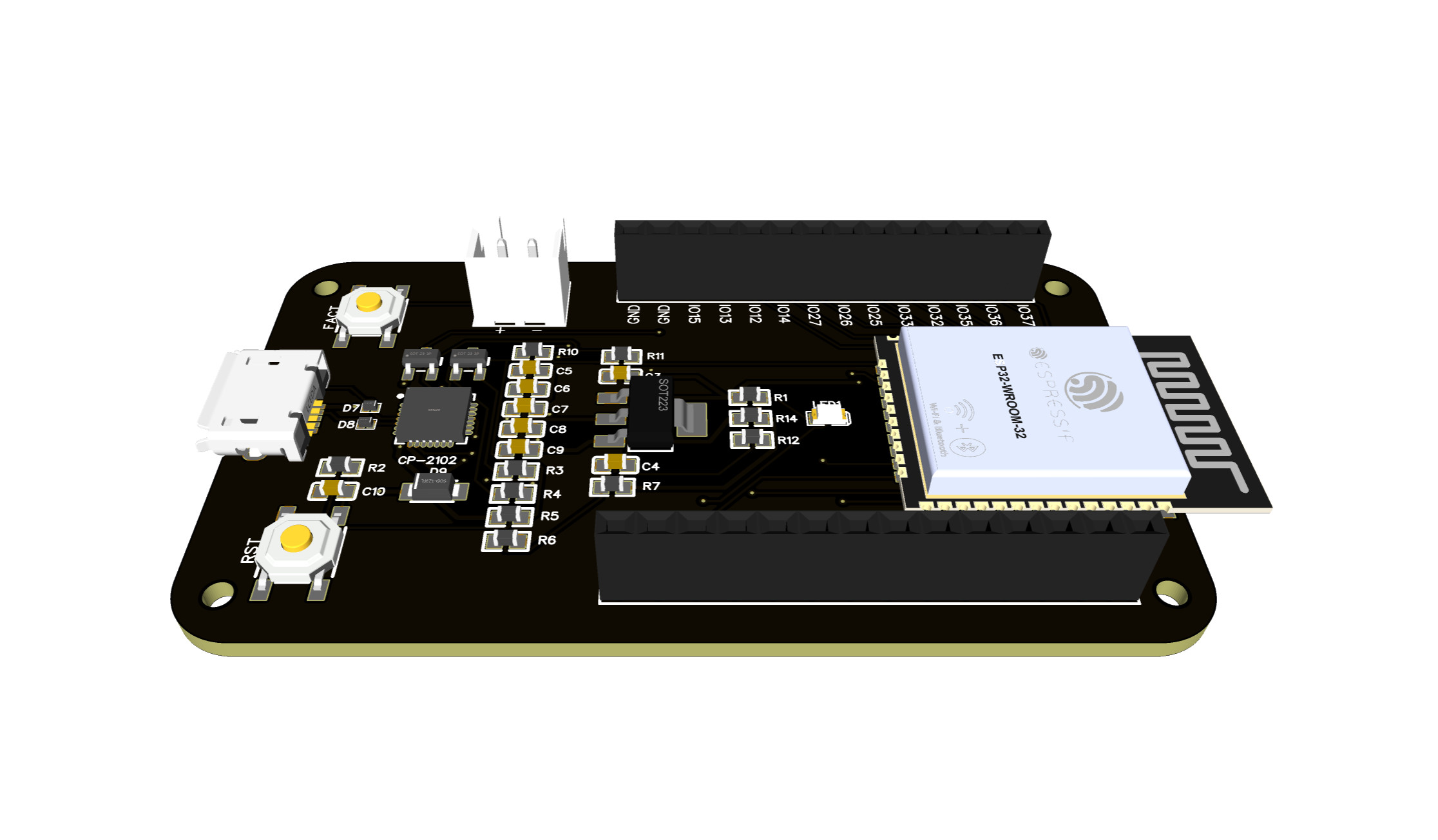
SignalIO Development Board is a device based on ESP32 SoC for IoT application development, hardware prototyping and design. SignalIO Development Board includes:
- On-board USB-UART programmer
- AMS 1117 3.3V 1A LDO
- Battery charge level monitoring (resistive divider)
- ESP32 WROOM SoC
The board is designed for non-professional users and is recommended for use in prototyping IoT systems, creating device concepts and learning programming and electronics. Improper use of the device can have unintended consequences for which the company is not responsible.
The board is based on a ESP32-WROOM SoC developed by Espressif with 40 nm technology. ESP32-WROOM integrates the following features:
- Microcontroller: Tensilica 32-bit Single-/Dual-core CPU Xtensa LX6
- Operating Voltage: 3.3V
- DIO: 25
- ADC: 6
- DAC: 2
- UARTs: 3
- SPIs: 2
- I2Cs: 3
- I2Ss: 2
- Flash Memory: 4 MB
- SRAM: 520 KB
- Clock Speed: 240 Mhz
- Wi-Fi: IEEE 802.11 b/g/n/e/i, Bluetooth/BLE:
- Integrated TR switch, balun, LNA, power amplifier and matching network
- WEP or WPA/WPA2 authentication, or open networks
- Special features:
- In-built Hall sensor
- In-built temperature sensor (internal temperature monitoring)
- Touch sensor interface
More detailed information about SoC can be found on Espressif official documentation (https://www.espressif.com/sites/default/files/documentation/esp32_datasheet_en.pdf).
Device have 28 general purpose input/output (GPIO) pins. Most of it can be used as digital and analog I/O. The Next picture illustrates pinmap diagram of the device.

First Boot
After power is applied, the device will give a signal in the form of LED blinking with an interval of 0.5 seconds. When you start the device for the first time, you need to set up a Wi-Fi network connection. After turning on the power and initializing the interfaces, the device will enter the Wi-Fi access point mode, after connecting to the access point, the device will give access to the web interface for configuring Wi-Fi connections. After the Wi-Fi connection is established, the system will give access to the interface configuration menu and network interactions. When entering the configuration menu for the first time, the system will ask for a username and password. The standard login is Signalio_sensor, the password is root1234 (it is highly recommended changing it in the process of use).
The device comes with two types of SignalIO proprietary firmware:
- Basic firmware
- OTA firmware
Sometimes the device may come without firmware. In this case, the device must be flashed with the current firmware version using the SignalIO Simplified utility. The current firmware version can be obtained on the project’s GIthub page - https://github.com/SignalIO-Team.
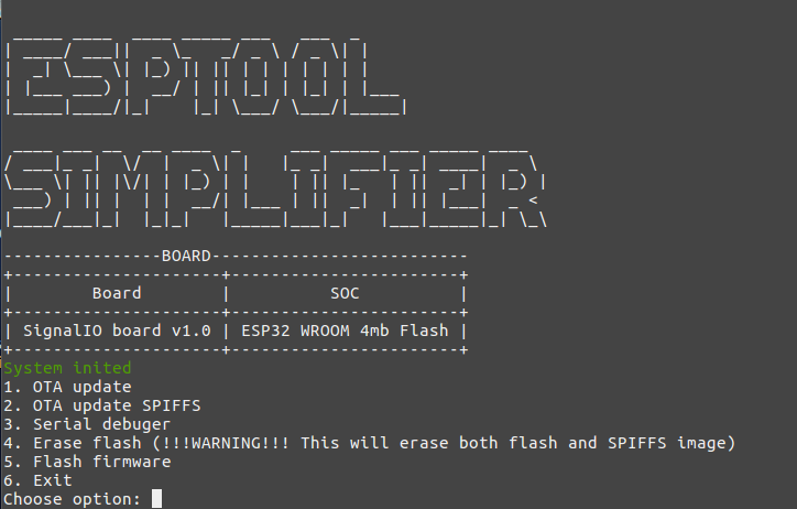
SignalIO-Simplify
SignalIO Simplify - simple utility for SignalIO Development Board. Its functions:
- OTA firmware and SPIFFS image update
- Upload firmware via USB-UART
- Serial port monitor
- Erase flash
This utility allows you to upload new firmware and print debugging information into serial monitor. Firmware folder stores firmware.bin (can be redefined in config file) image, data folder stores spiffs.bin (can be redefined in config file) image and config folder stores config.json file. JSON Config structure:
{
  "port": "YourSerialPort",
  "port_speed": "9600",
  "ota_ip":"YourDeviceIP",
  "ota_password":"YourDevicePassword",
  "ota_username": "YourDeviceUsername",
  "firmware_path": "firmware/firmware.bin",
  "spiffs_path": "data/spiffs.bin",
  "flash":"4MB",
  "start_addr":"0x10000"
}
This software also require python 2.8^, esptool.py and some external libraries which is listed in requirements.txt file.
To start the utility use this command:
Windows:
python __init__.py
Linux/Unix:
If you need to use serial debugger on Linux/Unix system you should also check if serial port available with command
ls /dev/tty*
Output should be: /dev/ttyUSB* or /dev/ttyACM* You should also set ACL for the serial port with command
sudo chmod 777 /dev/ttyUSB*
Then you can run the utility
sudo python __init__.py
NOTE
SignalIO Simplify Utility currently only been tested with Linux/Unix operating system. As an alternative to SignalIO Simplify, esptool can be used in the Windows system.
Upload New Firmware via SignalIO-Simplify
There are two ways to flash a device using SignalIO Simplify:
- Firmware with OTA update
- Direct upload of the firmware as a binary file into the device memory (wrapper over esptool)
In the first case, it is enough to configure the device in the firmware update mode in the settings item and select the OTA update option. The binary file located in the firmware folder will be loaded into the device memory after a while. For more information on OTA updates, see OTA Updates. In the case of uploading a binary file, the device must be connected directly to the PC. Next, select the Flash Firmware option, after which the firmware will be loaded into the device’s memory. It should also be remembered that the firmware consists of two binary files:
- Firmware.bin - the main firmware image;
- SPIFFS.bin - an image of the SPIFFS file system with the files necessary for work.
NOTE
At the first start, it is recommended to upload the firmware via Flash Firmware, as this will allow you to correctly mount the file system on the device. Alternatively, you can also use esptool.
Debugging via UART with SignalIO-Simplify
To use serial debugger you need to connect the board to the PC and setup serial monitor. SignalIO development board allows user to debug it via UART in few ways. First is to connect it directly via USB port. The Second is to connect it with the programmer with the TX and RX pins. This method can be used in case if inbuilt USB-UART prog In the second case you need to use the USB-UART-TTL programmer. The RX TX pins of the programmer must be connected in accordance with the next scheme:
Programmer pin —- Board pin
TX       -->       RX
RX       -->       TX
GND      -->       GND
After connecting the board to the PC, you need to configure the SignalIO Simplify utility by entering the necessary parameters in the config.json file, launch the utility and select the Serial debug option, after which debug information will appear in the port monitor.
Setup Wi-Fi connection
The Wi-Fi network is configured when the device is turned on for the first time. At the first start, the device will try to connect to the Wi-Fi network and if it fails, it will open the Wi-Fi manager.
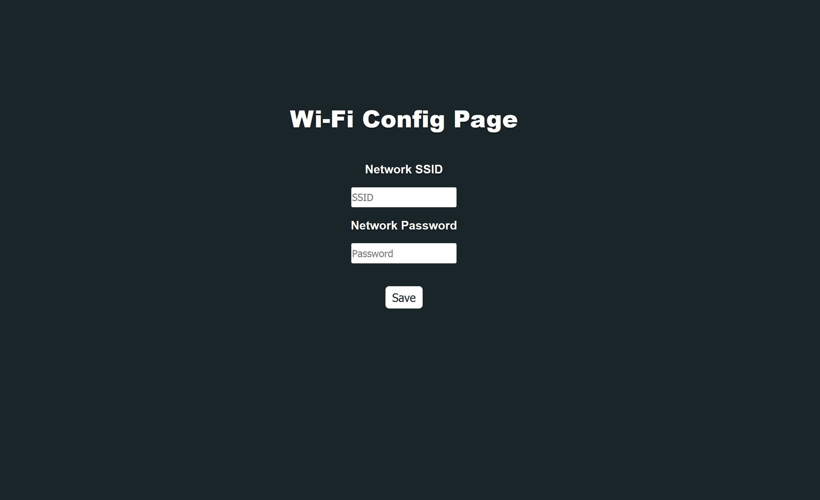
Wi-Fi manager will scan existing Wi-Fi networks and display them on the monitor. After that, the manager will launch a local web server with a form for entering the SSID and password.
After entering and checking all the parameters, press the Save button. If the configuration has been saved in the device memory correctly, the following message will be displayed.
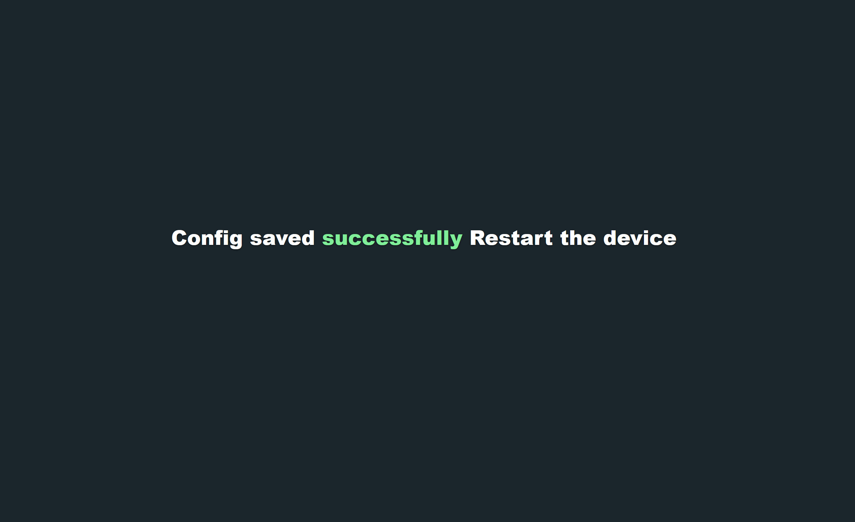
If an error occurs while saving the configuration, the following message will be displayed

After successful operation of setting up a Wi-Fi network, restart the device by pressing the RST button.
After rebooting, the device will automatically connect to the Wi-Fi network. If you need to reset the existing Wi-Fi network settings, you can use the FACTORY RESET option by pressing the FACT button
Configuration menu
The configuration menu is the main part of the device configuration system. In this menu it is possible:
- Configure connections to MQTT 3.3.1
- Select the required module and configure the GPIO port
- Set “DeepSleep” mode settings
- Set up an account
- Initialize OTA updates
To configure the main interfaces of the device, go to the “Config” item. At this point, there are three main cards with configurations:
- Interface config
- MQTT config
- DeepSleep config
Interface config
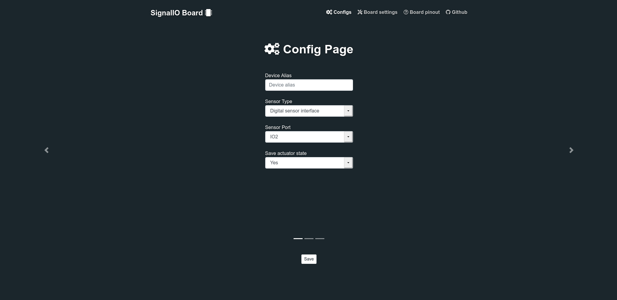
In this card, the interfaces of the microcontroller are configured and the modules with which the device will work are selected.
This card consists of the following fields:
- Device Alias - device identifier
- Sensor Type - list of available sensor and actuators
- Sensor Port - list of available digital/analog IO
- Save actuator state - flag for saving actuator state (for example relay state can be saved and restored in case of power fault)
MQTT
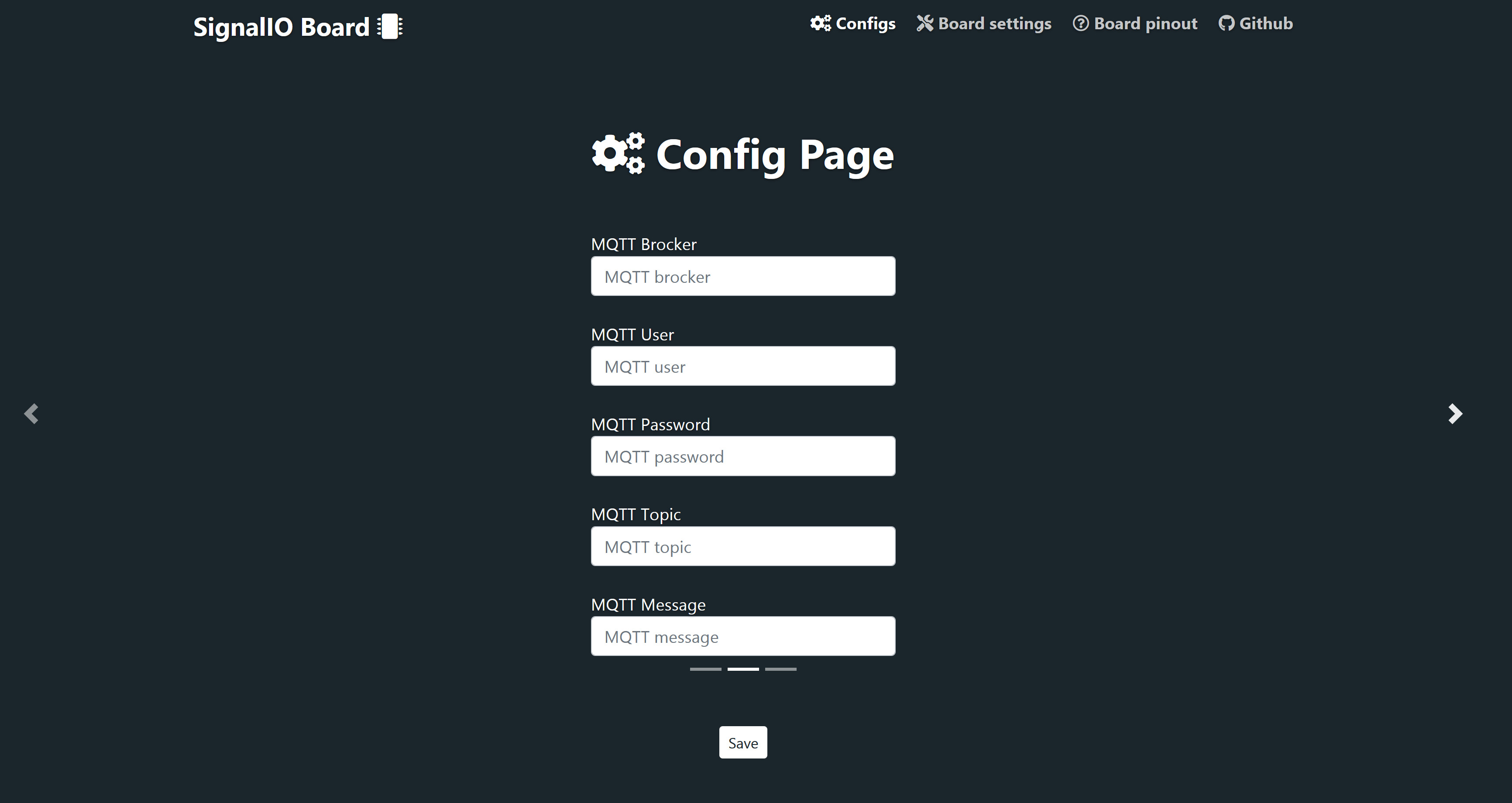
This card is needed to set up an MQTT connection. MQTT is the main communication protocol of the system. To configure it, you must fill in all the fields in the MQTT menu item.
The card consists of the following fields:
- MQTT Broker - URL/IP of the MQTT broker
- MQTT User - username for MQTT broker
- MQTT Password - password for broker
- MQTT Topic - topic on which device will publish data
- MQTT Message - message that will trigger the actuator device
DeepSleep
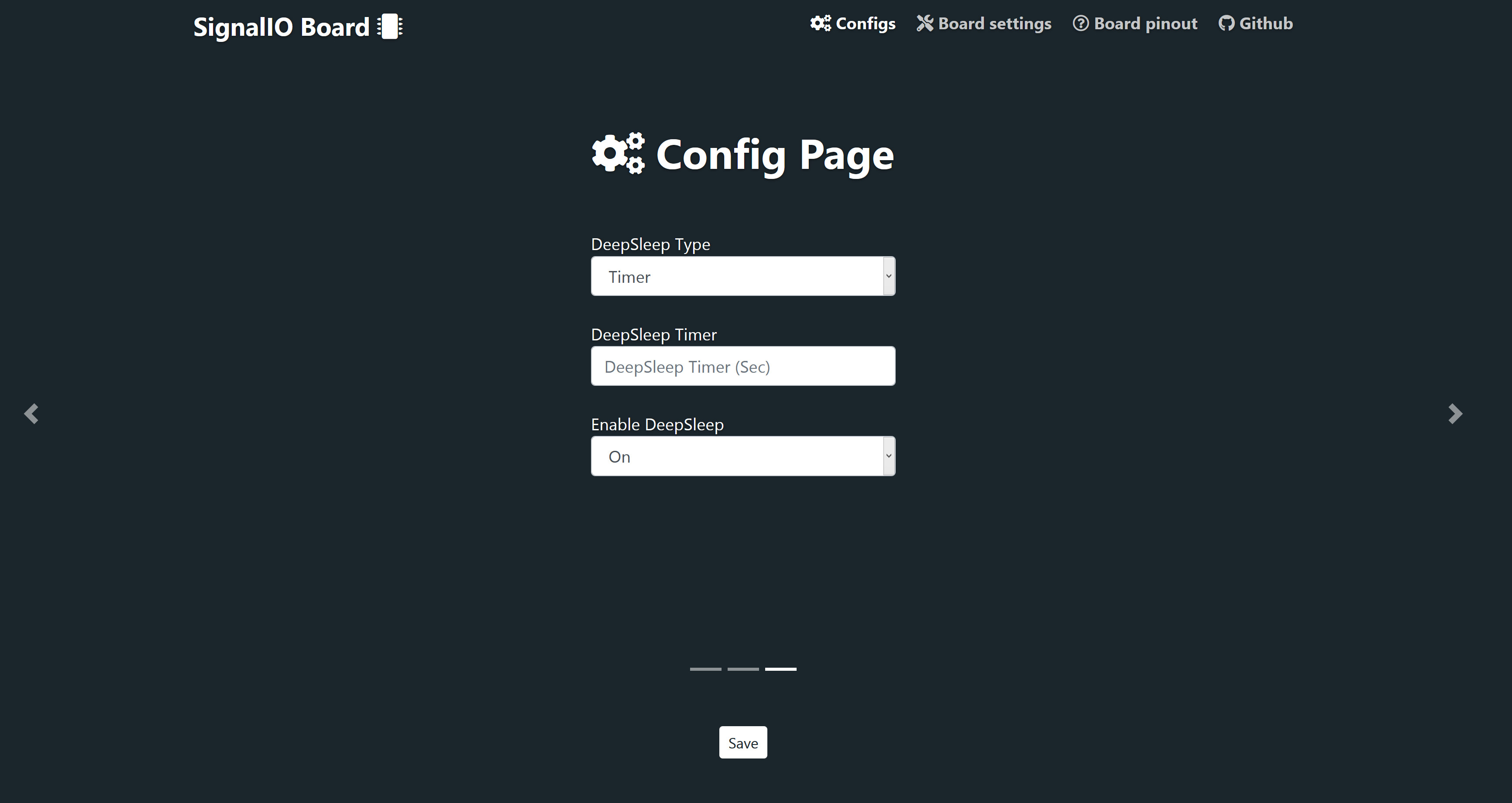
This card is needed to configure DeepSleep operating mode
The card consists of the following fields:
- DeepSleep Type - list of available DeepSleep modes (can be used as timer, in this case device will be triggered by the internal interruption, or as Trigger, in this case device will be triggered by the external interruption)
- DeepSleep Timer - interval with which device will be triggered with the internal interruptor
- Enable DeepSleep - enable or disable DeepSleep
Module selection
The system provides the ability to connect a number of digital, analog sensors and actuators (for a complete, currently, the list of devices supported by the firmware is given in the datasheet).
SignalIO Web App Connetion
To connect the device to the SignalIO Web Platform first you need to login to the dashboard.
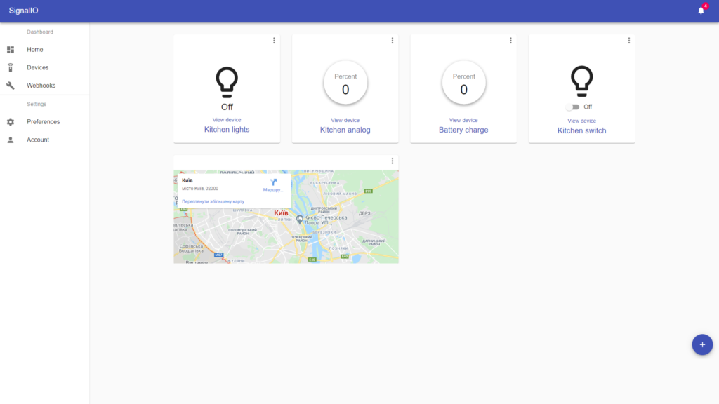
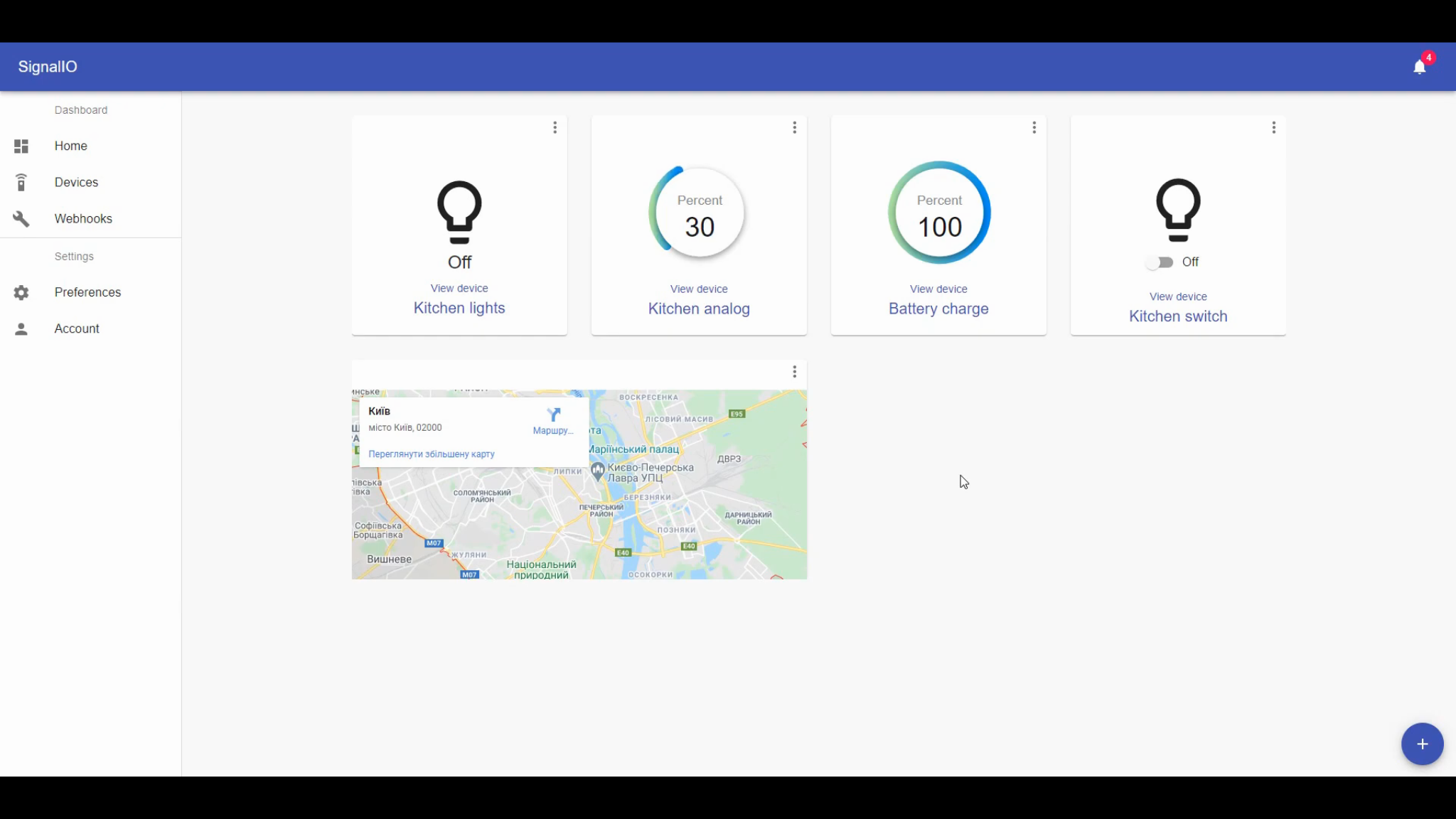
The Next step is to add a new “plugin” to your dashboard and then connect the device to it. To do so you need to press on the “plus” sign at the bottom of the dashboard working panel. Then you need to proceed through all of the options. The process is shown in the following pictures:
Picture 1
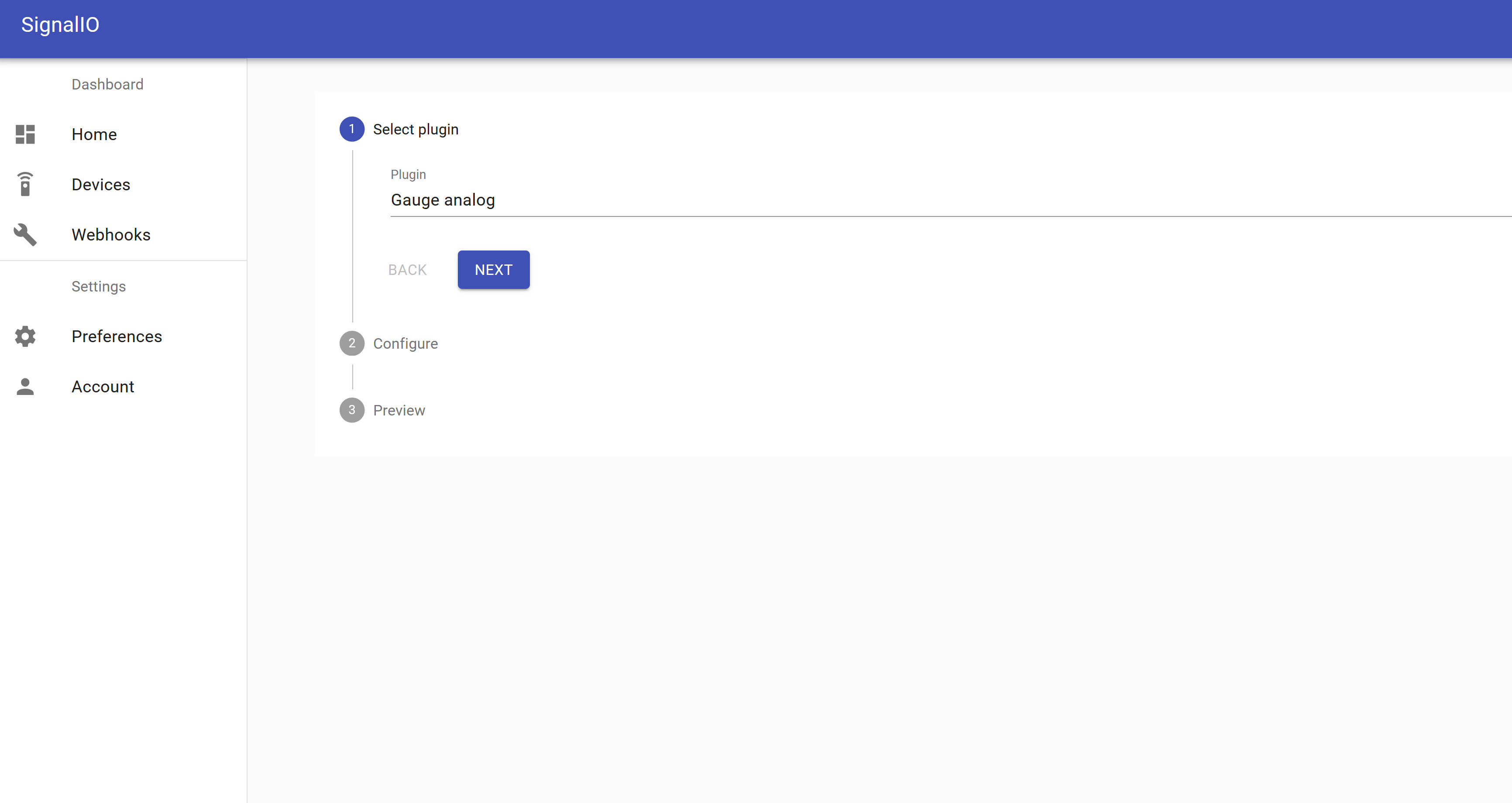
Picture 2
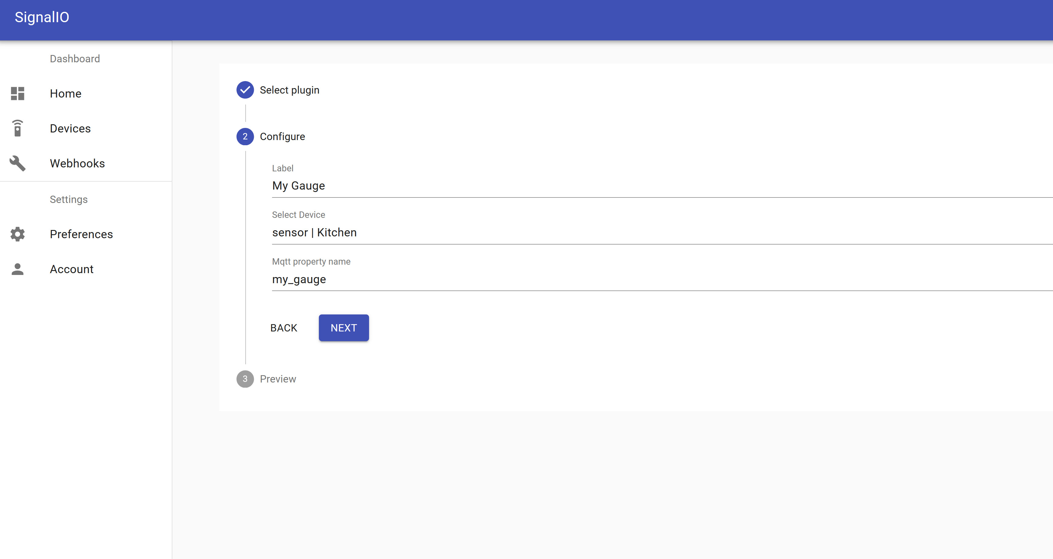
Picture 3
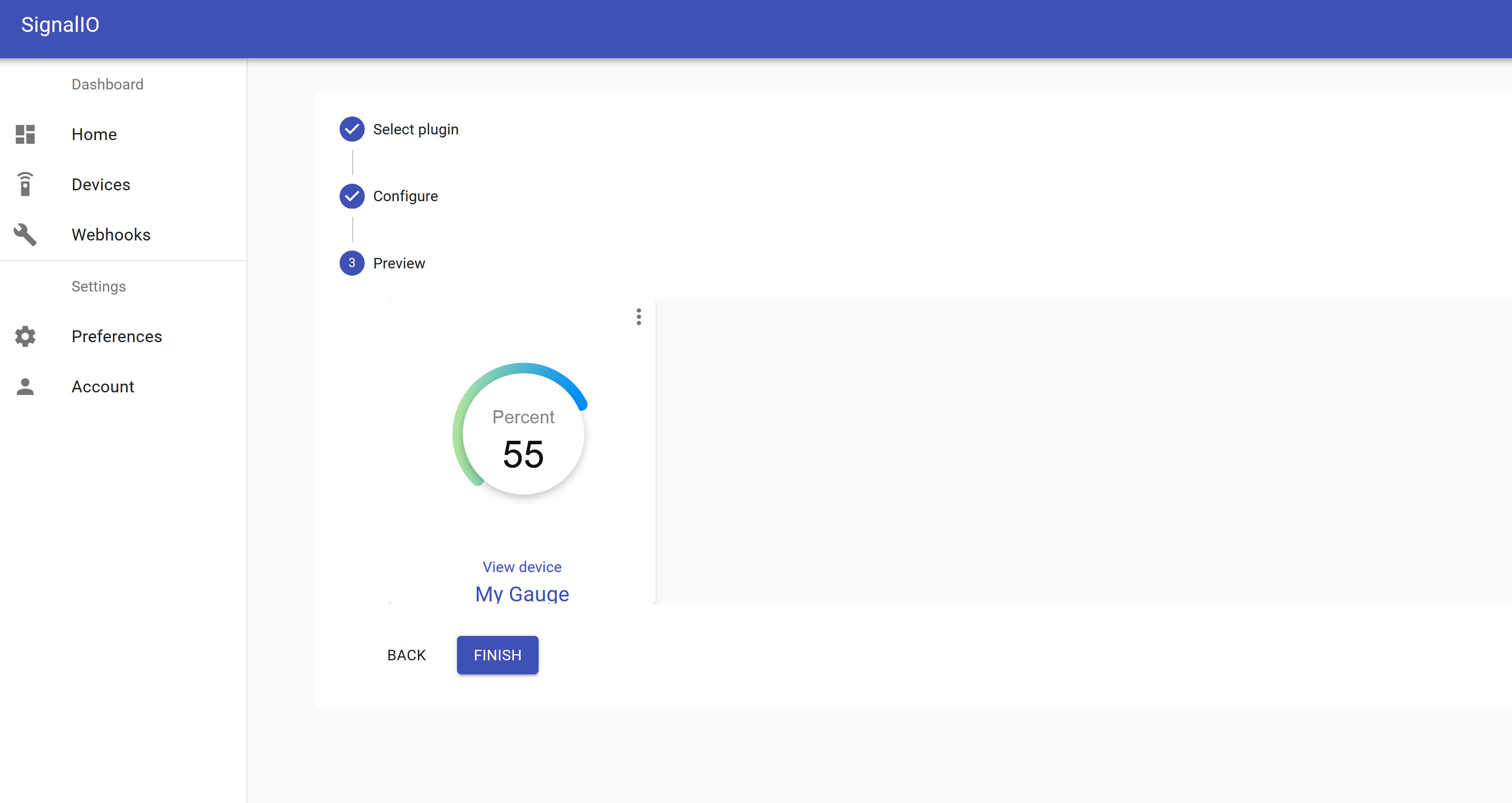
After that MQTT credentials should appear in “Device” menu. To connect to the platform you need to use generated topic, username, password and device alias.
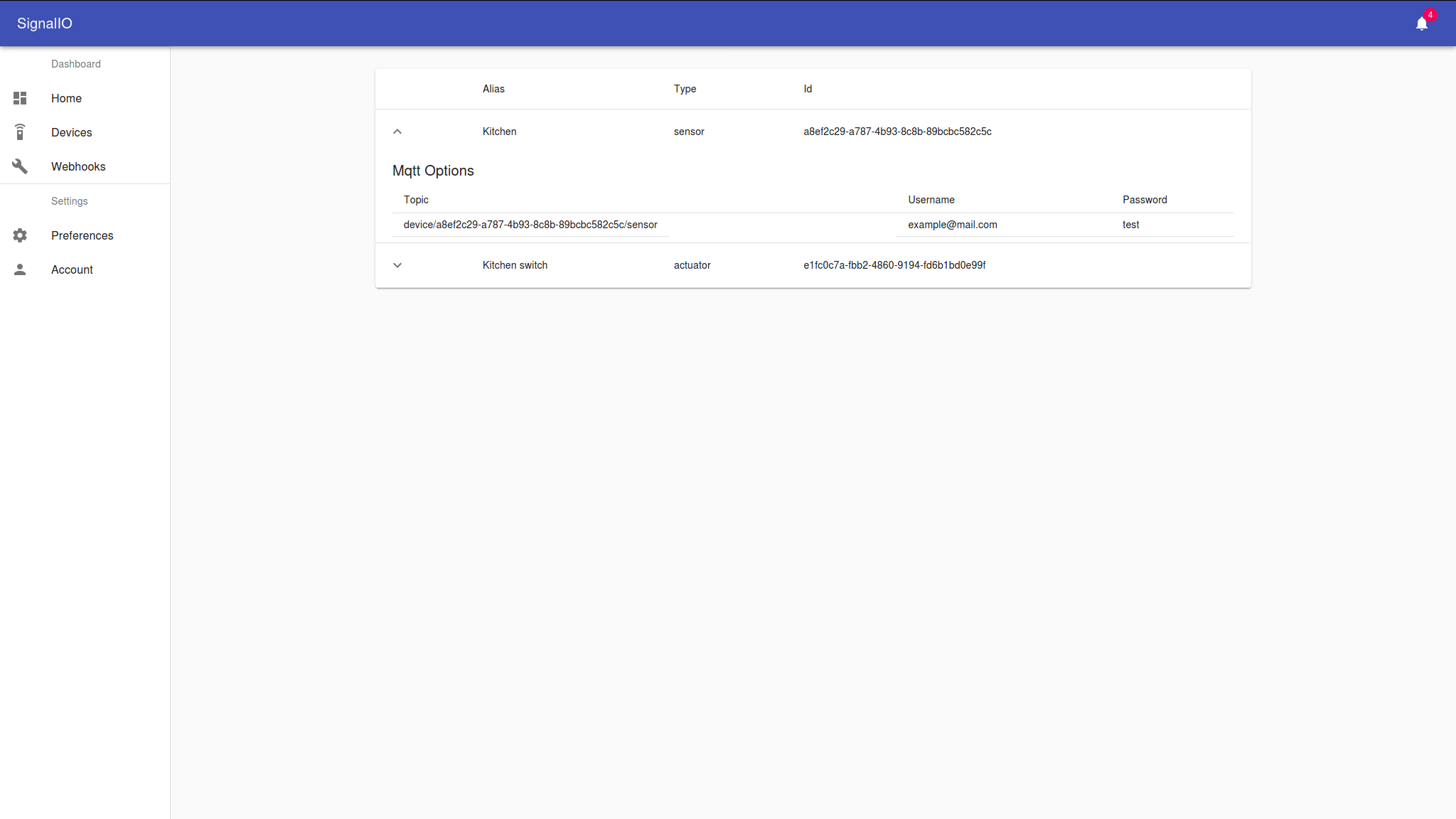
Finally, the device should publish some events, and it should appear on the dashboard.
Changing access credentials
To change device access credentials you should simply press on button Change Auth Creds in **Board settings section. After that modal window should appear.
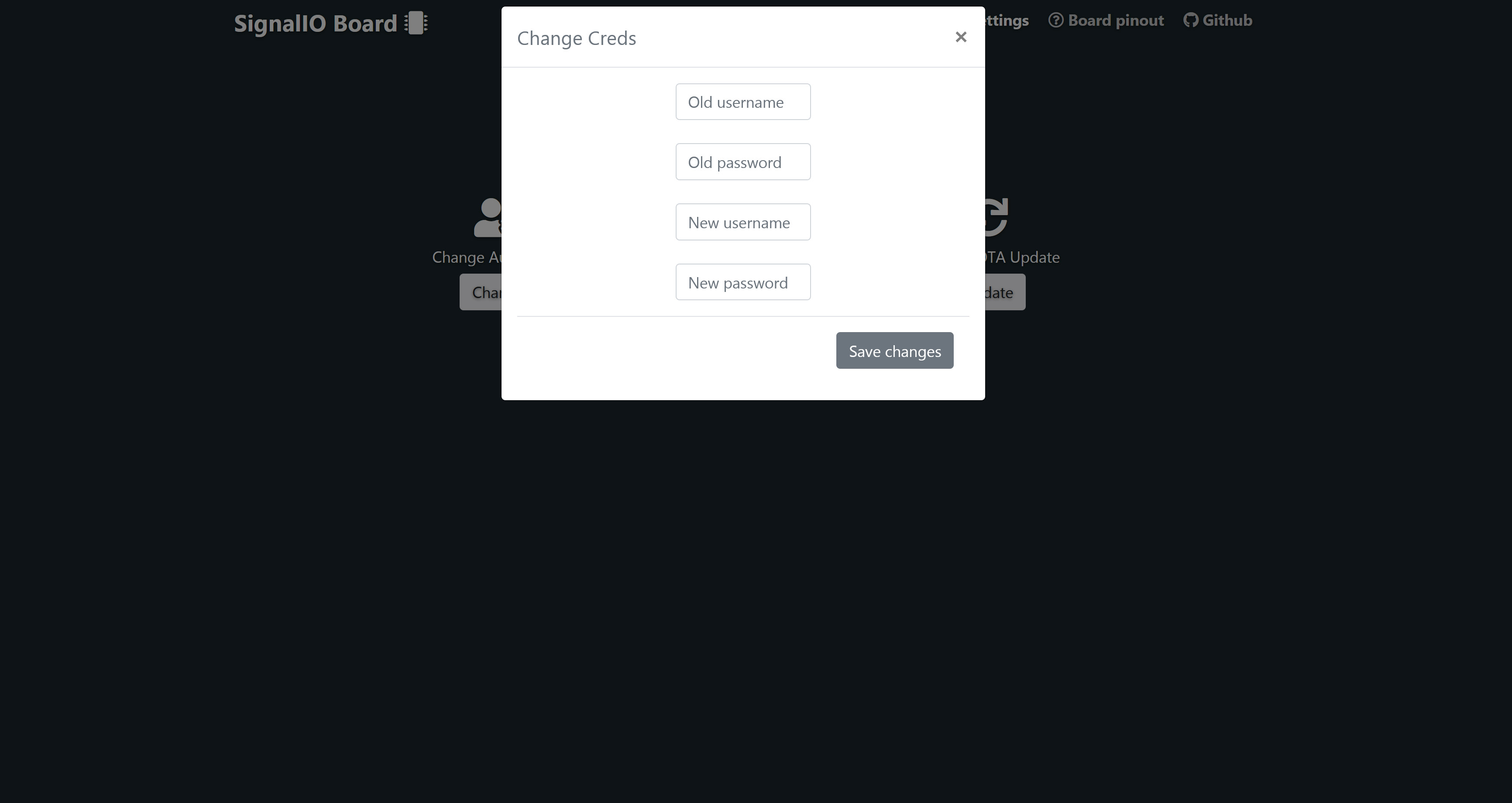
Next you need to fill all of the necessary fields you need to press Save changes button and then reboot the device via RST button. After the reboot you should be able to login into your device with new credentials. It is also possible to reset auth credentials with the FACTORY RESET button. You simply need to press FACT button and wait until the procedure is complete.
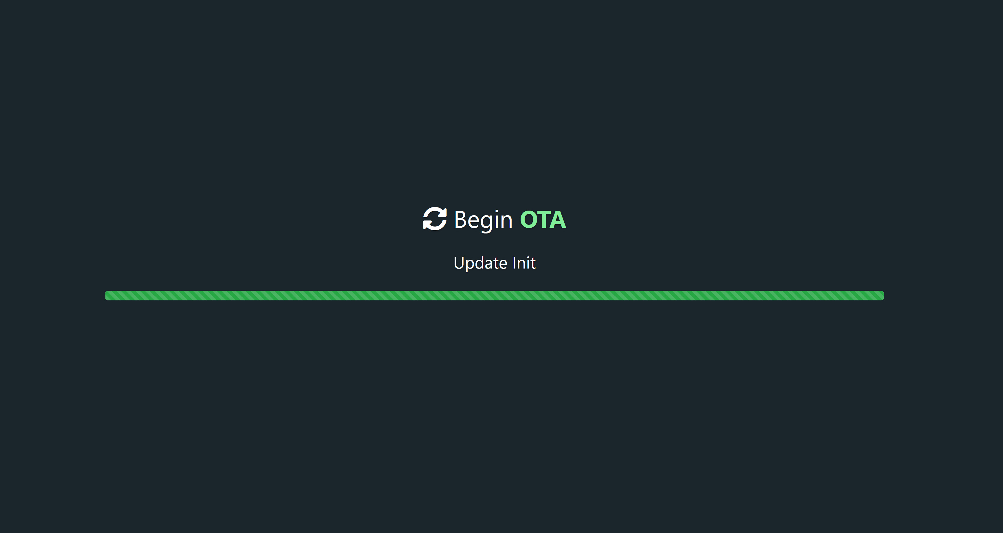
OTA Updates
To perform OTA update you will need to press on button OTA Update ** in **Board settings section. After that page with an OTA message will appear.
Next you’ll need a SignalIO-Simplify utility.
To perform OTA update with the SignalIO-Simplify you need to download the SignalIO Firmware from the project GitHub and put it into directory firmware (the path can be changed in config.json file). Next you need to put SPIFFS.bin into “data folder” (this path can also be changed).
Then you need to perform the next actions:
- First you should upload SPIFFS image into the device by choosing option OTA update SPIFFS
- Then you need to reboot the device and initialize OTA Update again
- At last you need to upload firmware.bin by choosing option OTA update and reboot the device.